 LabVIEW has three often-used floating palettes that you can place in a convenient spot on your screen: the Tools palette, the Controls palette, and the Functions palette. You can move them around by clicking on their title bar and dragging. Close them just like you would close any window in your operating system. If you decide you want them back, select the palette you want from the View menufor example, View>>Tools Palette opens the Tools palette.
Controls and Functions Palettes
You will be using the Controls palette a lot, because that's where you select the controls and indicators that you want on your front panel. You will probably use the Functions palette even more often, because it contains the functions and structures used to build a VI.
The Controls and Functions palettes are unique in several ways. Most importantly, the Controls palette is only visible when the front panel window is active, and the Functions palette is only visible when the block diagram window is active. Both palettes have subpalettes containing the objects you need to access. As you pass the cursor over each subpalette button in the Controls and Functions palettes, you will notice that the subpalette's name appears in a tip strip beneath the mouse pointer (see Figure 40).

Figure 40. Controls palette
To select an object in the subpalette, click the mouse button over the object, and then click on the front panel or block diagram to place it where you want it.
Palette Item Categories
At the top level of the palettes are several "Categories," such as Modern, System, Classic, Express, Addons, Favorites, and others. You can expand and close these categories, by clicking on them, to navigate the tree of items and subcategories that are available within the palette.
One great category is Favorites (this is only present on the Functions palette, not the Controls palette). You can use this to group together items that you access frequently. When you find a function, structure, VI, or subpalette that you really like, right-click on the object and select Add Item to Favorites from the shortcut menu. This will add the object to the Favorites category, for quick and easy access.
Showing and Hiding Palette Categories
You can choose which categories you want to appear on the Controls or Functions palettes by pressing the View button and then selecting categories from the Always Visible Categories submenu. If you want all of the categories to be visible, select the Show All Categories option from the Always Visible Categories submenu (see Figure 41).

Figure 41. The Always Visible Categories
submenu of the palette View button
If a category is not selected in the Always Visible Categories, then you will not normally see it in the palette. However, you can temporarily display all of the categories by clicking on the double "down" arrows at the very bottom of the palette, as shown in Figure 42. You can hide those categories again by clicking on the double "up" arrows at the very bottom of the palette, as shown in Figure 43.

Figure 42. Functions palette with only
the "always visible" categories visible

Figure 43. Functions palette with all categories visible
Reordering Palette Categories
You can reorder the palette categories by right-clicking on them and choosing Move this Category Up, Move this Category Down, or Move to Top (Expand by Default). Additionally, you can drag and drop the categories within the list by clicking on the two vertical grab-bars (||) to the left of the category text.
Palette View Formats
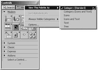
The way that you navigate the palettes can be changed by choosing a different palette View Format. Pressing the View button at the top of a palette will open a menu. In the View This Palette As submenu, you can choose from six different View Formats, as shown in Figure 44.
You can reorder the palette categories by right-clicking on them and choosing Move this Category Up, Move this Category Down, or Move to Top (Expand by Default). Additionally, you can drag and drop the categories within the list by clicking on the two vertical grab-bars (||) to the left of the category text.
Palette View Formats
The way that you navigate the palettes can be changed by choosing a different palette View Format. Pressing the View button at the top of a palette will open a menu. In the View This Palette As submenu, you can choose from six different View Formats, as shown in Figure 44.

Figure 44. The View This Palette As submenu
of the palette View button menu showing the
currently selected checked palette view format
Category (Standard) is the default View Format, and the one shown throughout this tutorial.
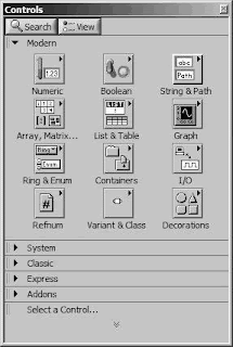
Category (Icons and Text), shown in Figure 45, is similar to Category (Standard), except that each item's name appears directly beneath its icon.
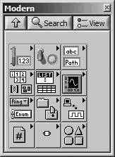
Icons, shown in Figure 46, is the format that most are familiar with from previous versions of LabVIEW. Each subpalette and item is represented by an icon. When you mouse-over an item, its name appears at the top of the palette.
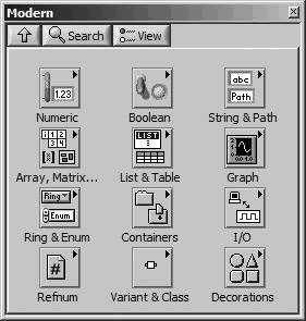
Icons and Text, shown in Figure 47, is similar to Icons, except that each item's name appears directly beneath its icon.
Category (Icons and Text), shown in Figure 45, is similar to Category (Standard), except that each item's name appears directly beneath its icon.

Figure 45. "Category (Icons and Text)" palette view format
Icons, shown in Figure 46, is the format that most are familiar with from previous versions of LabVIEW. Each subpalette and item is represented by an icon. When you mouse-over an item, its name appears at the top of the palette.

Figure 46. "Icons" palette view format
Icons and Text, shown in Figure 47, is similar to Icons, except that each item's name appears directly beneath its icon.

Figure 47. "Icons and Text" palette view format
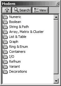
Text, shown in Figure 48, is minimal. It behaves like the Icons and Icons and Text formats, where clicking on a subpalette navigates down into that subpalette. Subpalettes are represented by folders with names, and items are represented by their name.
Tree, shown in Figure 49, is also minimal, having only folder icons and item names. However, it behaves more like the Category formats, having a tree hierarchy.
The "Icons," "Icons and Text," and "Text" palette view formats all have an "up" button (see Figure 50), which, when pressed, returns you to the previous ("owning") palettesince these view formats are not a tree view. You can search for a specific item in a palette by clicking on the spyglass icon (see Figure 50).
There is another way to navigate palettes that some people find a little easier. Instead of each subpalette replacing the current palette, you can pass through subpalettes in a hierarchical manner without them replacing their parent palettes. You can do this by right-clicking (Windows) or control-clicking (Mac OS X) the subpalette icons (see Figure 51).
Note that some subpalettes have subpalettes containing more objects; these are denoted by a little triangle in the upper-right corner of the icon and a raised appearance (see Figure 52). We'll discuss specific subpalettes and their objects in the next chapter.
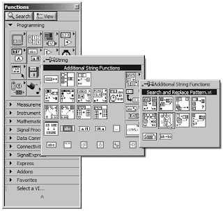

Figure 48. "Text" palette view format
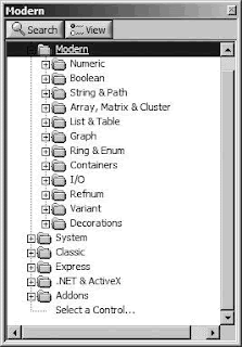
Tree, shown in Figure 49, is also minimal, having only folder icons and item names. However, it behaves more like the Category formats, having a tree hierarchy.

Figure 49. "Tree" palette view format
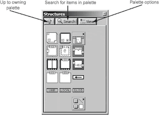
The "Icons," "Icons and Text," and "Text" palette view formats all have an "up" button (see Figure 50), which, when pressed, returns you to the previous ("owning") palettesince these view formats are not a tree view. You can search for a specific item in a palette by clicking on the spyglass icon (see Figure 50).

Figure 50. The buttons at the top of each palette are used for navigation and configuration options.
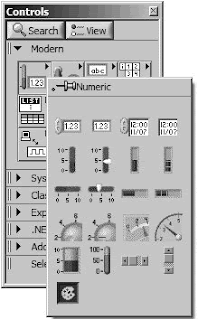
There is another way to navigate palettes that some people find a little easier. Instead of each subpalette replacing the current palette, you can pass through subpalettes in a hierarchical manner without them replacing their parent palettes. You can do this by right-clicking (Windows) or control-clicking (Mac OS X) the subpalette icons (see Figure 51).

Figure 51. A floating subpalette created by right-clicking on a subpalette icon
Note that some subpalettes have subpalettes containing more objects; these are denoted by a little triangle in the upper-right corner of the icon and a raised appearance (see Figure 52). We'll discuss specific subpalettes and their objects in the next chapter.

Figure 52. Functions palette with two levels of floating subpalettes visible


