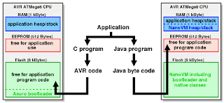
The NanoVM is a java virtual machine for the Atmel AVR ATmega8 CPU, the member of the AVR CPU family used e.g. in the DLR Asuro robot, manufactured by AREXX engineering. With the NanoVM, the Asuro can be programmed in the popular Java language using the standard Sun JDK. The NanoVM and its tools are distributed under the GPL and can be used on other AVR based systems as well.
The NanoVM for Asuro replaces the original firmware of the Asuro with a Java virtual machine capable of running a subset of the virtual machine command set. This enables e.g. the Asuro to interpret java bytecode and to run simple java programs like e.g. this one.
The NanoVM is a very resource aware implementation of the java vm. The Asuro version including a boot loader and several native classes fit into the 8kBytes flash rom of the Asuros AVR ATmega8 CPU. The complete 512 Byte EEPROM space of the CPU are available as Java program space and 75% of the 1 kByte RAM space are available to the running Java program.
More information about The NanoVM - Java for the AVR click here
Sunday, July 5, 2009
Displaying SubVIs as Expandable Nodes [LabVIEW Tutorial]
SubVIs may be viewed as either icons or expandable nodes. Express VIs are viewed as expandable nodes, by default. To view a subVI as an expandable node, right-click on it and uncheck the View As Icon option by selecting it from the pop-up menu, as shown in Figure 71. This will cause the subVI's appearance to change, such that its icon is surrounded by a yellow background, as shown in Figure 72.
We can resize the subVI vertically, which causes inputs and outputs to appear below the subVI's icon, as shown in Figure 73. Note that inputs and outputs made available are no longer available to the left and right of the subVI's icon.
You can also show and hide inputs and outputs from the subVI's pop-up menu, using the Select Input/Output submenu to change an input/output, Insert Input/Output to insert a new input/output, and Remove Input/Output to remove an input/output (see Figure 74).
Figure 71. SubVI with View As Icon setting enabled, as also indicated in its visible pop-up menu
Figure 72. SubVI with View As Icon setting disabled, appearing as an expandable node
We can resize the subVI vertically, which causes inputs and outputs to appear below the subVI's icon, as shown in Figure 73. Note that inputs and outputs made available are no longer available to the left and right of the subVI's icon.
Figure 73. Resizing (expanding) a subVI configured as an expandable node
You can also show and hide inputs and outputs from the subVI's pop-up menu, using the Select Input/Output submenu to change an input/output, Insert Input/Output to insert a new input/output, and Remove Input/Output to remove an input/output (see Figure 74).
Figure 74. Selecting the visible inputs and outputs of a subVI configured as an expandable, from its pop-up menu
Thursday, June 25, 2009
Exploit The SoundCard as Oscilloscope
Thanks to Konstantin Zeldovich
Oscilloscope for Windows version 2.51 (Oscilloscope 2.51) is an application showing how home PC peripherials, such as a sound card, can be used in an unconventional way, emulating industrial ADC hardware. The Oscilloscope provides a complete functionality of a "standalone" scope in a familiar Windows ennvironment.
The Oscilloscope allows you, for example:
- to study in real time any signal envelope,
- to measure frequencies
- to study realtime signal spectra,
- to plot Lissajous patterns.
- to measure a cross-correlation coefficient of two signals
(In general, to do most things you can do with an oscilloscope and a spectrum analyzer).
Not surprisingly, the Oscilloscope has several drawbacks too:
- non-calibrated amplitude level (hard to use as digital multimeter),
- relatively low bandwidth (20 Hz - 20 kHz),
- possibility of damage of a PC when connecting to an unknown signal source. (See Precautions ).
Specifications:
Dual trace digital storage oscilloscope with realtime spectrum analyzer and correlometer.
Buffer length: 52 ms
Bandwidth: 20 Hz - 20 kHz max
Input level: about 2 VAC, limited by sound card capabilities
Display refresh: ca. 6 fps
Data export: disk file or Windows clipboard, text format
Click here to download the oscilloscope software
Tuesday, June 23, 2009
USB Sniffer With SnoopyPro
SnoopyPro is a tool for advanced USB programmers. It allows you to record each URB sent to and received from a USB device. This traces can be saved, loaded, edited, printed and combined into new traces.
WARNING: You might damage your system with this tool. Don't use it if you don't know what you're doing!!!! We're not responsible for anything that happens to you, your system, your devices, your marriage, etc. etc.
SUPPORTED OPERATING SYSTEMS:
Tested by the authors on Windows 98, Windows 2000, Windows XP
INSTALLATION/USE:
1. Run SnoopyPro.exe from whereever you have saved it.
2. Open up the USB devices window with F2.
3. Choose 'Unpack Drivers' from the 'File' menu.
4. Choose 'Install Service' from the 'File' menu.
5. Locate the device you want to sniff.
6. Right-click on it and choose 'Install and Restart'.
7. Wait for the magic to happen...
Click Here To Download SnoopyPro
Saturday, June 20, 2009
The Toolbar in LabVIEW
The Toolbar, located at the top of LabVIEW windows, contains buttons you will use to control the execution of your VI, as well as text configuration options and commands to control the alignment and distribution of objects (see Figure 59). You'll notice that the Toolbar has a few more options in the block diagram than in the front panel, and that a few editing-related options disappear when you run your VI. If you're not sure what a button does, hold the cursor over it until a tip strip appears, describing its function.
Figure 59. Toolbar
Run Button
Run Button (Active)
Run Button (Broken)
The Run button, which looks like an arrow, starts VI execution when you click on it. It changes appearance to active when a VI is actually running. When a VI won't compile, the run button appears broken.
Continuous Run Button
The Continuous Run button causes the VI to execute over and over until you hit the stop button. It's kind of like a GOTO statement (sort of a "programming no-no"), so use it sparingly.
Abort Button
The Abort button, easily recognizable because it looks like a tiny stop sign, becomes active when a VI begins to execute; otherwise, the Abort button is grayed out. You can click on this button to halt the VI.
Using the Abort button is like pulling the power cord on your computer. Your program will stop immediately rather than coming to a graceful end, and data integrity can be lost this way. You should always code a more appropriate stopping mechanism into your program, as we will demonstrate later.
Pause Button
The Pause button pauses the VI so that you can use single-step debugging options such as step into, step over, and step out. Hit the Pause button again to continue execution.
Step Into Button
Step Over Button
Step Out Button
The single-step buttonsStep Into, Step Over, and Step Outforce your VI to execute one step at a time so you can troubleshoot.
Execution Highlight Button
The Execution Highlight button causes the VI to highlight the flow of data as it passes through the diagram. When execution highlight is on, you can see intermediate data values in your block diagram that would not otherwise appear.
Retain Wire Values
The Retain Wire Values button causes the VI's wires to store the value that flowed through them the last time the VI executed. This is very useful for debugging. You can view the value stored in a wire by placing a probe on the wire. The probe value will be set to the value stored in the wire.
Warning Button
The Warning button appears if you have configured your VI to show warnings and you have any warnings outstanding. You can list the warnings by clicking on the button. A warning is not an error; it just alerts you that you are doing something you may not have intended (for example, if there are objects on the block diagram that are hidden behind other objects and cannot be seen).
Friday, June 19, 2009
Comm Sniffer (From Knightsoft.net)
CommSniffer is a valuable tool for technicians, engineers and software developers designing/debugging serial port related projects, it is an advanced COM/RS232 Serial port data viewer / analyzer. View and send (all 256) ASCII/Binary data. Main features include:
Click here to download Comm Sniffer "FREE..."
- Supports COM1 to COM16.
- Baud rates from 110 to 115200.
- Export transactions session to an ASCII file.
- Designed for ease of use.
- Ultra fast display rate.
- Runs in Windows 9X/2000/XP.
- Capture/send data to/from serial port.
- Built in data converter ASCII/Binary/Hex.
- Built in search.
Click here to download Comm Sniffer "FREE..."
Pic Baud Rate Calculator V2.1 (208Kb zip Win32 App)
PIC Baud Calculator - a FREE utility to calculate the SPBRG value for the PIC processors with on board Uart. Simply enter the Clock speed and the desired Baud rate and hit calculate. The SPBRG value is shown for both BRG High and Low, including the difference error. On some older PIC uarts, the BRG High setting causes intermittent UART errors.
V2.1 now supports systems that require 'commas' instead of 'points' in floating point numbers.
his utility is provided FREE of charge and as such comes with no technical support or guarantee! by downloading it you agree to these terms. If you are unsure of the validity of the output from this utility, don't use it. :)
Click here to download PIC Baud Calculator
Thursday, June 18, 2009
RTU and CPU Used in SCADA and Benefits Using SCADA System
Remote terminal units
An RTU (sometimes referred to as a remote telemetry unit) as the title implies, is a standalone data acquisition and control unit, generally microprocessor based, which monitors and controls equipment at some remote location from the central station. Its primary task is to control and acquire data from process equipment at the remote location and to transfer this data back to a central station. It generally also has the facility for having its configuration and control programs dynamically downloaded from some central station. There is also a facility to be configured locally by some RTU programming unit. Although traditionally the RTU communicates back to some central station, it is also possible to communicate on a peer-to-peer basis with other RTUs. The RTU can also act as a relay station (sometimes referred to as a store and forward station) to another RTU, which may not be accessible from the central station.
Small sized RTUs generally have less than 10 to 20 analog and digital signals, medium sized RTUs have 100 digital and 30 to 40 analog inputs. RTUs, having a capacity greater than this can be classified as large.
A typical RTU configuration is shown in Figure below:
A short discussion follows on the individual hardware components. Typical RTU hardware modules include:
• Control processor and associated memory
• Analog inputs
• Analog outputs
• Counter inputs
• Digital inputs
• Digital outputs
• Communication interface(s)
• Power supply
• RTU rack and enclosure
Control processor (or CPU)
This is generally microprocessor based (16 or 32 bit) e.g. 68302 or 80386. Total memory capacity of 256 kByte (expandable to 4 Mbytes) broken into three types:
1 EPROM (or battery backed RAM) = 256 kByte
2 RAM = 640 kByte
3 Electrically erasable memory (flash or EEPROM) = 128 kByte
A mathematical processor is a useful addition for any complex mathematical calculations. This is sometimes referred to as a coprocessor.
Communication ports – typically two or three ports either RS-232/RS-422/RS-485 for:
• Interface to diagnostics terminal
• Interface to operator station
• Communications link to central site (e.g. by modem)
Diagnostic LEDs provided on the control unit ease troubleshooting and diagnosis of problems (such as CPU failure/failure of I/O module etc).
Another component, which is provided with varying levels of accuracy, is a real-time clock with full calendar (including leap year support). The clock should be updated even during power off periods. The real-time clock is useful for accurate time stamping of events.
A watchdog timer is also required to provide a check that the RTU program is regularly executing. The RTU program regularly resets the watchdog time. If this is not done within a certain time-out period the watchdog timer flags an error condition (and can reset the CPU).
Considerations and benefits of SCADA system
Typical considerations when putting a SCADA system together are:
• Overall control requirements
• Sequence logic
• Analog loop control
• Ratio and number of analog to digital points
• Speed of control and data acquisition
• Master/operator control stations
• Type of displays required
• Historical archiving requirements
• System consideration
• Reliability/availability
• Speed of communications/update time/system scan rates
• System redundancy
• Expansion capability
• Application software and modeling
Obviously, a SCADA system’s initial cost has to be justified. A few typical reasons for implementing a SCADA system are:
• Improved operation of the plant or process resulting in savings due to optimization of the system
• Increased productivity of the personnel
• Improved safety of the system due to better information and improved control
• Protection of the plant equipment
• Safeguarding the environment from a failure of the system
• Improved energy savings due to optimization of the plant
• Improved and quicker receipt of data so that clients can be invoiced more quickly and accurately
• Government regulations for safety and metering of gas (for royalties & tax etc)
Electric Circuits,7th Edtion
Electric Circuits, Seventh Edition features a redesigned art program, a new four-color format, and 75% new or revised problems throughout. In the midst of these changes, the book retains the goals that have made it a best-seller: 1) To build an understanding of concepts and ideas explicitly in terms of previous learning; 2) To emphasize the relationship between conceptual understanding and problem solving approaches; 3) To provide readers with a strong foundation of engineering practices. Chapter topics include Circuit Variables; Circuit Elements; Simple Resistive Circuits; Techniques of Circuit Analysis; The Operational Amplifier; Inductors, Capacitors, and Mutual Inductance; Response of First-Order RL and RC Circuits; Natural and Step Responses of RLC Circuits; Sinusoidal Steady-State Analysis; and more. For anyone interested in circuit analysis.
Click Here To Download This Ebook
SMT USB AVR Programmer With ATTINY2313SO
Thanks to : Ayman El-Khashab, phd, pe
Here is the first iteration of the AVR µISP programmer. This is based on the usbtinyisp from adafruit, that was in turn based on Dick Streefland's USBTiny and the USB stack at www.obdev.at. but smaller and with all SMT parts except for the 10 and 6 pin headers.
I chose to spin my own design since I wanted to use it in a few different modes.First, I wanted to use a standard ISP cable. Second, I wanted to be able to insert pins from the programmer into boards without requiring the ISP header pins populated. Third, I wanted the capability to attach QFP and SOIC clips. And finally, by placing a female connector on the bottom of the programmer, it is possible to place the entire programmer atop a board header.
There are only a few differences in this design
100 Ω series resistors instead of 1500 Ω
Mini USB connector
Blue LED instead of green
Pin mapping of the AVR is slightly different
The entire board is 46mm x 20mm (about 1.8" by 0.8"). The hex code is available below, but if you want to build the code yourself, be certain to use GCC 3.x version. The 4.x versions do not do well with the AVR code size and this program is extremely tight in the ATTiny2313. Secondly, you will need a way to load the initial firmware into the AVR. I used my old standby, the SP12 that I have used for several years.
Since it is based on other designs, this one works with the avrdude programmer as well. Unfortunately the USB organization has come down on the people parcelling out PIDs, so you may have a difficult time getting another one if you so desire.
In addition to using this for programming AVRs, it may be used as a generic SPI controller or JTAG interface. It does not have enough pins for TMS, TCK, TDI, TRST, and TDO. However, many parts (and every Xilinx part I've ever used) do not have a TRST so with just the 3 outputs and 1 input it is possible to program Xilinx FPGAs and CPLDs. You may need a pullup on TDO. Then you can use the playxsvf program to sent a bitstream to the part. I currently use a variant of this for programming the ps3toothfairy devices. I implemented the same thing with the SP12, but it is parallel only and support for parallel ports is dwindling.
Modifying the code
If you decide to make some design changes and spin your own board, you'll need to edit the c code and the header file. The pins are well labeled except for a couple of writes to PORTD. Just search for PORTD in the spi.c code and update for your particular configuration. It is wise to read through the USB headers as well as the usbtiny.h file to understand what you can and cannot change in your design.
If you build the code and it is too large for the device, you have a couple of options. If it is a few bytes off, you can try reducing the string size in usbtiny.h. If it is much too large, you probably have something wrong in your compile or build settings. Check the makefile and be certain you aren't building with the gcc 4.x toolchain.
You can operate the device with avrdude. You may need to add in usb support depending on your platform (it is needed for cygwin).
Anyway, enjoy and thanks to the folks that made previous designs possible.
Build it
Here are pictures of the schematic and gerbers. Download the design below. We may make some available for purchase (especially since you need some method to initially program the micro). The build is not difficult with an iron, but it is likely easier with a toaster oven or hotplate reflow. (I've built a couple all with an iron in a couple of minutes). Click the images to get a larger view. The crystal goes either direction since the pins are at the corners.
Here is the BOM. None of the parts are particularly critical, other than you need to make sure to get the proper footprint.
Downloads
Note that updates were made to the Eagle files after the prototype and I haven't fabbed any from this design yet. It should work (as it was just moving some traces), but as with anything you download, trust-but-verify.
Firmware Source & Hex Code
Eagle Sch & PCB
License
The USBtiny software is licensed under the terms of the GNU General Public License as published by the Free Software Foundation, either version 2 of the license, or (at your option) any later version. A copy of the GPL version 2 license can be found in the file COPYING.
Wednesday, June 17, 2009
Analog Electronics with LabVIEW
From the Back Cover
The hands-on, simulation-based introduction to analog electronics.
Analog Electronics with LabVIEW is the first comprehensive introduction to analog electronics that makes full use of computer simulation. Kenneth L. Ashley introduces analog electronics through a series of theory/project sections, in which theoretical presentations correlate directly with circuit measurement and analysis projects. The results of experiments are used to extract device model parameters used in subsequent electronic circuit analysis, providing a significant enhancement in the understanding of modern, computer-based electronic-circuit simulation. Readers will master not only the fundamentals of analog electronics, but also data acquisition and circuit simulation with LabVIEW, basic circuit-solution computation with Mathcad, and circuit simulation with Cadence Schematics or Capture. Coverage includes:
* Elementary analog circuit analysis, including the resistor voltage divider and MOSFET DC gate voltage, MOSFET drain current-source equivalent, amplifier frequency response, and more
* Fundamentals of transistors and voltage amplification
* Characterization of MOS transistors for circuit simulation
* Common-source amplifiers, MOSFET source-follower buffer stage, differential amplifier stage, and MOSFET current sources
* Operational amplifiers: resistor negative feedback approaches and capacitor-based applications
* Development of a Basic CMOS Operational Amplifier
* LabVIEW tutorial with emphasis on analog electronics, the discrete nature of compute data acquisition, and LabVIEW measurement VIs such as the autoranging DC voltmeter
* Characterization of the BJT for circuit simulation including linear modeling
* BJT NPN common-emitter amplifier, including emitter degeneration and current-source PNP load with emitter degeneration
For those new to LabVIEW, the book also contains a complete introductory tutorial with emphasis relevant to analog-electronics applications.
The accompanying CD-ROM includes a complete copy of LabVIEW 6 Student Edition Software, along with all the LabVIEW, Mathcad, and Schematics (or Capture) files you need to perform the experiments and exercises in this book, plus samples of all project measurement and data files for measurement simulation.
Click Here to download Analog Electronics with LabVIEW
Password : www.freebookspot.com
Tuesday, June 16, 2009
Transformerless Power Supply
Electric Shock Hazard. In the UK,the neutral wire is connected to earth at the power station. If you touch the "Live" wire, then depending on how well earthed you are, you form a conductive path between Live and Neutral. DO NOT TOUCH the output of this power supply. Whilst the output of this circuit sits innocently at 12V with respect to (wrt) the other terminal, it is also 12V above earth potential. Should a component fail then either terminal will become a potential shock hazard.
If you are not experienced in dealing with it, then leave this project alone.Although Mains equipment can itself consume a lot of current, the circuits we build to control it, usually only require a few milliamps. Yet the low voltage power supply is frequently the largest part of the construction and a sizeable portion of the cost.
This circuit will supply up to about 20ma at 12 volts. It uses capacitive reactance instead of resistance; and it doesn't generate very much heat.The circuit draws about 30ma AC. Always use a fuse and/or a fusible resistor to be on the safe side. The values given are only a guide. There should be more than enough power available for timers, light operated switches, temperature controllers etc, provided that you use an optical isolator as your circuit's output device. (E.g. MOC 3010/3020) If a relay is unavoidable, use one with a mains voltage coil and switch the coil using the optical isolator.C1 should be of the 'suppressor type'; made to be connected directly across the incoming Mains Supply. They are generally covered with the logos of several different Safety Standards Authorities. If you need more current, use a larger value capacitor; or put two in parallel; but be careful of what you are doing to the Watts. The low voltage 'AC' is supplied by ZD1 and ZD2.
The bridge rectifier can be any of the small 'Round', 'In-line', or 'DIL' types; or you could use four separate diodes. If you want to, you can replace R2 and ZD3 with a 78 Series regulator. The full sized ones will work; but if space is tight, there are some small 100ma versions available in TO 92 type cases. They look like a BC 547. It is also worth noting that many small circuits will work with an unregulated supply. You can, of course, alter any or all of the Zenner diodes in order to produce a different output voltage. As for the mains voltage, the suggestion regarding the 110v version is just that, a suggestion. I haven't built it, so be prepared to experiment a little.
I get a lot of emails asking if this power supply can be modified to provide currents of anything up to 50 amps. It cannot. The circuit was designed to provide a cheap compact power supply for Cmos logic circuits that require only a few milliamps. The logic circuits were then used to control mains equipment (fans, lights, heaters etc.) through an optically isolated triac. If more than 20mA is required it is possible to increase C1 to 0.68uF or 1uF and thus obtain a current of up to about 40mA. But 'suppressor type' capacitors are relatively big and more expensive than regular capacitors; and increasing the current means that higher wattage resistors and zener diodes are required. If you try to produce more than about 40mA the circuit will no longer be cheap and compact, and it simply makes more sense to use a transformer.
Saturday, June 6, 2009
AVR Simulator IDE
AVR Simulator IDE is powerful application that supplies AVR developers with user-friendly graphical development environment for Windows with integrated simulator (emulator), BASIC compiler, assembler, disassembler and debugger.
The main application window shows all AVR microcontroller internal registers status (general purpose working and I/O registers, internal data SRAM and program counter), mnemonics of the last executed instruction, mnemonics of the next instruction that will be executed, clock cycles and instructions counter and real time duration of the
simulation.
Click here to download AVR Simulator IDE
Friday, June 5, 2009
PIC Simulator IDE for PIC 16F Family
PIC Simulator IDE is powerful application that supplies PIC developers with user-friendly graphical development environment for Windows with integrated simulator (emulator), BASIC compiler, assembler, disassembler and debugger.
The main application window shows all PIC microcontroller internal registers status, mnemonics of the last executed instruction, mnemonics of the next instruction that will be executed, clock cycles and instructions counter and real time duration of the simulation.
Click here to download PIC Simulator IDE for PIC 16F Family
Sunday, May 31, 2009
Floating Palettes in LabVIEW
LabVIEW has three often-used floating palettes that you can place in a convenient spot on your screen: the Tools palette, the Controls palette, and the Functions palette. You can move them around by clicking on their title bar and dragging. Close them just like you would close any window in your operating system. If you decide you want them back, select the palette you want from the View menufor example, View>>Tools Palette opens the Tools palette.
Controls and Functions Palettes
You will be using the Controls palette a lot, because that's where you select the controls and indicators that you want on your front panel. You will probably use the Functions palette even more often, because it contains the functions and structures used to build a VI.
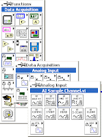
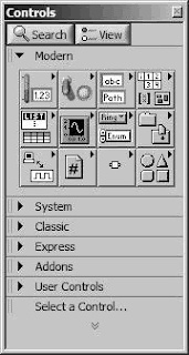
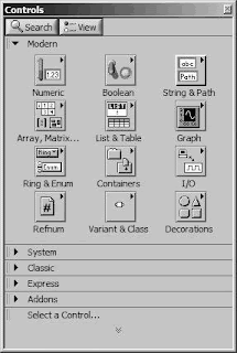
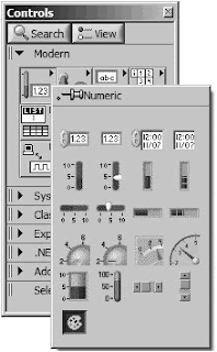
The Controls and Functions palettes are unique in several ways. Most importantly, the Controls palette is only visible when the front panel window is active, and the Functions palette is only visible when the block diagram window is active. Both palettes have subpalettes containing the objects you need to access. As you pass the cursor over each subpalette button in the Controls and Functions palettes, you will notice that the subpalette's name appears in a tip strip beneath the mouse pointer (see Figure 40).
To select an object in the subpalette, click the mouse button over the object, and then click on the front panel or block diagram to place it where you want it.
Palette Item Categories
At the top level of the palettes are several "Categories," such as Modern, System, Classic, Express, Addons, Favorites, and others. You can expand and close these categories, by clicking on them, to navigate the tree of items and subcategories that are available within the palette.
One great category is Favorites (this is only present on the Functions palette, not the Controls palette). You can use this to group together items that you access frequently. When you find a function, structure, VI, or subpalette that you really like, right-click on the object and select Add Item to Favorites from the shortcut menu. This will add the object to the Favorites category, for quick and easy access.
Showing and Hiding Palette Categories
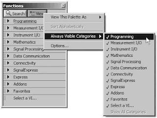
You can choose which categories you want to appear on the Controls or Functions palettes by pressing the View button and then selecting categories from the Always Visible Categories submenu. If you want all of the categories to be visible, select the Show All Categories option from the Always Visible Categories submenu (see Figure 41).
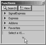
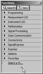
If a category is not selected in the Always Visible Categories, then you will not normally see it in the palette. However, you can temporarily display all of the categories by clicking on the double "down" arrows at the very bottom of the palette, as shown in Figure 42. You can hide those categories again by clicking on the double "up" arrows at the very bottom of the palette, as shown in Figure 43.
Controls and Functions Palettes
You will be using the Controls palette a lot, because that's where you select the controls and indicators that you want on your front panel. You will probably use the Functions palette even more often, because it contains the functions and structures used to build a VI.
The Controls and Functions palettes are unique in several ways. Most importantly, the Controls palette is only visible when the front panel window is active, and the Functions palette is only visible when the block diagram window is active. Both palettes have subpalettes containing the objects you need to access. As you pass the cursor over each subpalette button in the Controls and Functions palettes, you will notice that the subpalette's name appears in a tip strip beneath the mouse pointer (see Figure 40).
Figure 40. Controls palette
To select an object in the subpalette, click the mouse button over the object, and then click on the front panel or block diagram to place it where you want it.
Palette Item Categories
At the top level of the palettes are several "Categories," such as Modern, System, Classic, Express, Addons, Favorites, and others. You can expand and close these categories, by clicking on them, to navigate the tree of items and subcategories that are available within the palette.
One great category is Favorites (this is only present on the Functions palette, not the Controls palette). You can use this to group together items that you access frequently. When you find a function, structure, VI, or subpalette that you really like, right-click on the object and select Add Item to Favorites from the shortcut menu. This will add the object to the Favorites category, for quick and easy access.
Showing and Hiding Palette Categories
You can choose which categories you want to appear on the Controls or Functions palettes by pressing the View button and then selecting categories from the Always Visible Categories submenu. If you want all of the categories to be visible, select the Show All Categories option from the Always Visible Categories submenu (see Figure 41).
Figure 41. The Always Visible Categories
submenu of the palette View button
If a category is not selected in the Always Visible Categories, then you will not normally see it in the palette. However, you can temporarily display all of the categories by clicking on the double "down" arrows at the very bottom of the palette, as shown in Figure 42. You can hide those categories again by clicking on the double "up" arrows at the very bottom of the palette, as shown in Figure 43.
Figure 42. Functions palette with only
the "always visible" categories visible
Figure 43. Functions palette with all categories visible
Reordering Palette Categories
You can reorder the palette categories by right-clicking on them and choosing Move this Category Up, Move this Category Down, or Move to Top (Expand by Default). Additionally, you can drag and drop the categories within the list by clicking on the two vertical grab-bars (||) to the left of the category text.
Palette View Formats
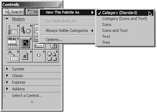
The way that you navigate the palettes can be changed by choosing a different palette View Format. Pressing the View button at the top of a palette will open a menu. In the View This Palette As submenu, you can choose from six different View Formats, as shown in Figure 44.
Figure 44. The View This Palette As submenu
of the palette View button menu showing the
currently selected checked palette view format
Category (Standard) is the default View Format, and the one shown throughout this tutorial.
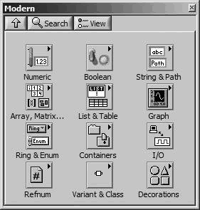
Category (Icons and Text), shown in Figure 45, is similar to Category (Standard), except that each item's name appears directly beneath its icon.
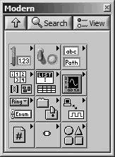
Icons, shown in Figure 46, is the format that most are familiar with from previous versions of LabVIEW. Each subpalette and item is represented by an icon. When you mouse-over an item, its name appears at the top of the palette.
Icons and Text, shown in Figure 47, is similar to Icons, except that each item's name appears directly beneath its icon.
Category (Icons and Text), shown in Figure 45, is similar to Category (Standard), except that each item's name appears directly beneath its icon.
Figure 45. "Category (Icons and Text)" palette view format
Icons, shown in Figure 46, is the format that most are familiar with from previous versions of LabVIEW. Each subpalette and item is represented by an icon. When you mouse-over an item, its name appears at the top of the palette.
Figure 46. "Icons" palette view format
Icons and Text, shown in Figure 47, is similar to Icons, except that each item's name appears directly beneath its icon.
Figure 47. "Icons and Text" palette view format
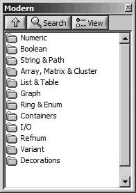
Text, shown in Figure 48, is minimal. It behaves like the Icons and Icons and Text formats, where clicking on a subpalette navigates down into that subpalette. Subpalettes are represented by folders with names, and items are represented by their name.
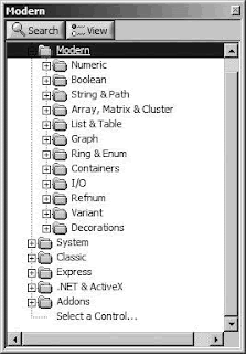
Tree, shown in Figure 49, is also minimal, having only folder icons and item names. However, it behaves more like the Category formats, having a tree hierarchy.
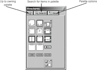
The "Icons," "Icons and Text," and "Text" palette view formats all have an "up" button (see Figure 50), which, when pressed, returns you to the previous ("owning") palettesince these view formats are not a tree view. You can search for a specific item in a palette by clicking on the spyglass icon (see Figure 50).
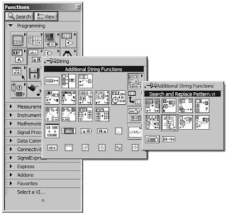
There is another way to navigate palettes that some people find a little easier. Instead of each subpalette replacing the current palette, you can pass through subpalettes in a hierarchical manner without them replacing their parent palettes. You can do this by right-clicking (Windows) or control-clicking (Mac OS X) the subpalette icons (see Figure 51).
Note that some subpalettes have subpalettes containing more objects; these are denoted by a little triangle in the upper-right corner of the icon and a raised appearance (see Figure 52). We'll discuss specific subpalettes and their objects in the next chapter.
Figure 48. "Text" palette view format
Tree, shown in Figure 49, is also minimal, having only folder icons and item names. However, it behaves more like the Category formats, having a tree hierarchy.
Figure 49. "Tree" palette view format
The "Icons," "Icons and Text," and "Text" palette view formats all have an "up" button (see Figure 50), which, when pressed, returns you to the previous ("owning") palettesince these view formats are not a tree view. You can search for a specific item in a palette by clicking on the spyglass icon (see Figure 50).
Figure 50. The buttons at the top of each palette are used for navigation and configuration options.
There is another way to navigate palettes that some people find a little easier. Instead of each subpalette replacing the current palette, you can pass through subpalettes in a hierarchical manner without them replacing their parent palettes. You can do this by right-clicking (Windows) or control-clicking (Mac OS X) the subpalette icons (see Figure 51).
Figure 51. A floating subpalette created by right-clicking on a subpalette icon
Note that some subpalettes have subpalettes containing more objects; these are denoted by a little triangle in the upper-right corner of the icon and a raised appearance (see Figure 52). We'll discuss specific subpalettes and their objects in the next chapter.
Figure 52. Functions palette with two levels of floating subpalettes visible
Subscribe to:
Posts (Atom)