Sunday, July 5, 2009

The NanoVM - Java for the AVR

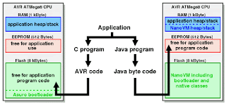
The NanoVM is a java virtual machine for the Atmel AVR ATmega8 CPU, the member of the AVR CPU family used e.g. in the DLR Asuro robot, manufactured by AREXX engineering. With the NanoVM, the Asuro can be programmed in the popular Java language using the standard Sun JDK. The NanoVM and its tools are distributed under the GPL and can be used on other AVR based systems as well.

The NanoVM for Asuro replaces the original firmware of the Asuro with a Java virtual machine capable of running a subset of the virtual machine command set. This enables e.g. the Asuro to interpret java bytecode and to run simple java programs like e.g. this one.


The NanoVM is a very resource aware implementation of the java vm. The Asuro version including a boot loader and several native classes fit into the 8kBytes flash rom of the Asuros AVR ATmega8 CPU. The complete 512 Byte EEPROM space of the CPU are available as Java program space and 75% of the 1 kByte RAM space are available to the running Java program.

More information about The NanoVM - Java for the AVR click here

Displaying SubVIs as Expandable Nodes [LabVIEW Tutorial]

SubVIs may be viewed as either icons or expandable nodes. Express VIs are viewed as expandable nodes, by default. To view a subVI as an expandable node, right-click on it and uncheck the View As Icon option by selecting it from the pop-up menu, as shown in Figure 71. This will cause the subVI's appearance to change, such that its icon is surrounded by a yellow background, as shown in Figure 72.


Figure 71. SubVI with View As Icon setting enabled, as also indicated in its visible pop-up menu


Figure 72. SubVI with View As Icon setting disabled, appearing as an expandable node

We can resize the subVI vertically, which causes inputs and outputs to appear below the subVI's icon, as shown in Figure 73. Note that inputs and outputs made available are no longer available to the left and right of the subVI's icon.


Figure 73. Resizing (expanding) a subVI configured as an expandable node

You can also show and hide inputs and outputs from the subVI's pop-up menu, using the Select Input/Output submenu to change an input/output, Insert Input/Output to insert a new input/output, and Remove Input/Output to remove an input/output (see Figure 74).


Figure 74. Selecting the visible inputs and outputs of a subVI configured as an expandable, from its pop-up menu

Thursday, June 25, 2009

Exploit The SoundCard as Oscilloscope

Thanks to Konstantin Zeldovich

Oscilloscope for Windows version 2.51 (Oscilloscope 2.51) is an application showing how home PC peripherials, such as a sound card, can be used in an unconventional way, emulating industrial ADC hardware. The Oscilloscope provides a complete functionality of a "standalone" scope in a familiar Windows ennvironment.

The Oscilloscope allows you, for example:
- to study in real time any signal envelope,
- to measure frequencies
- to study realtime signal spectra,
- to plot Lissajous patterns.
- to measure a cross-correlation coefficient of two signals
(In general, to do most things you can do with an oscilloscope and a spectrum analyzer).


Not surprisingly, the Oscilloscope has several drawbacks too:
- non-calibrated amplitude level (hard to use as digital multimeter),
- relatively low bandwidth (20 Hz - 20 kHz),
- possibility of damage of a PC when connecting to an unknown signal source. (See Precautions ).


Specifications:
Dual trace digital storage oscilloscope with realtime spectrum analyzer and correlometer.
Buffer length: 52 ms
Bandwidth: 20 Hz - 20 kHz max
Input level: about 2 VAC, limited by sound card capabilities
Display refresh: ca. 6 fps
Data export: disk file or Windows clipboard, text format

Click here to download the oscilloscope software